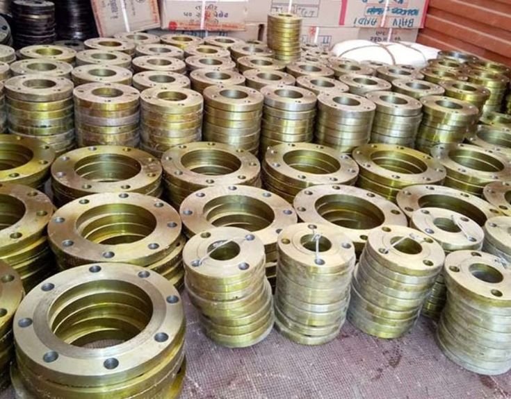
In a complex piping system, a flange may look like a simple ring of forged metal.It is anything but simple.
A flange sits at one of the most important interfaces in a piping network—between pipe and valve, pipe and pump, equipment and pipeline, or sometimes between generations of infrastructure that were never originally designed to work together.
When everything is correctly specified, the connection becomes almost invisible. When it is not, a seemingly minor dimensional mismatch can lead to leakage, installation delays, field modification, equipment damage, or costly downtime.
That is where custom flange engineering becomes more than an alternative to a standard catalogue component.
It becomes a way to solve a specific engineering problem.
Standard Is Useful. It Just Isn’t Universal.
Standardized flanges are the foundation of modern piping systems. They provide established dimensions, pressure classes, materials and connection configurations that make procurement and installation predictable.
But real projects rarely exist in a perfect catalogue environment.
Engineers may encounter:
- Existing equipment with unusual bolt patterns
- Legacy piping built to older specifications
- Non-standard pipe dimensions
- Special bore requirements
- Unusual pressure or temperature conditions
- Corrosive or chemically aggressive media
- Space and alignment limitations
- Retrofit equipment with different connection geometry
- Project-specific standards or certification requirements
In these situations, forcing a standard flange into the design can create more problems than it solves.
The better question is not:
“Which standard flange is closest?” It is:
“What flange geometry, material and configuration does this connection actually require?”
- A Flange Is a System Interface
- A flange does three jobs simultaneously.
- It creates a mechanical connection.
- It transfers loads between connected components.
And, together with the gasket and bolting system, it forms a pressure-containing seal.
That means flange performance depends on much more than outside diameter and bolt-hole count.
The engineering process may need to consider:
- Material grade
- Pressure and temperature
- Bore diameter
- Wall thickness
- Flange thickness
- Face configuration
- Bolt-hole pattern
- Bolt size
- Hub geometry
- Gasket arrangement
- Corrosion environment
- Thermal expansion
- Equipment interface
- Applicable manufacturing and inspection requirements
A custom flange therefore should not simply be viewed as a non-standard shape.
It is an engineered component designed around the conditions of a particular connection.
Where Custom Flanges Become Essential
- Retrofitting Existing Equipment
Retrofit projects are among the clearest examples of where standard components can fall short.
An existing facility may contain equipment installed decades ago. Its flange dimensions, drilling, face geometry or pressure requirements may no longer correspond to today’s commonly available configurations.
Replacing the entire system simply to accommodate a standard flange can be unnecessary and expensive.
A custom flange can act as the interface between the existing installation and the new equipment.
Instead of rebuilding a functioning section of the plant, the connection itself can be engineered to bridge the difference.
- Special Material Requirements
Not every process can rely on conventional carbon steel.
High temperatures, corrosive fluids, aggressive chemicals and demanding operating environments may require specialized alloys or specific material grades.
Material selection must therefore begin with the service conditions—not with whatever material happens to be readily available.
The flange must retain its mechanical and sealing performance throughout the expected operating environment.
- Non-Standard Dimensions
Sometimes the problem is purely geometric.
The required flange may have:
- A special outside diameter
- An unusual bolt circle
- A non-standard bore
- Increased thickness
- Modified hub dimensions
- Special face machining
- Custom connection geometry
These requirements can arise from existing equipment, unusual piping dimensions or project-specific design constraints.
This is where custom manufacturing eliminates the need to redesign the surrounding system simply because a catalogue component does not exist.
- Higher Mechanical Demands
Pressure is only one part of the loading picture.
A flange may also experience forces generated by:
- Thermal expansion
- Vibration
- Equipment movement
- Pipe weight
- Pressure fluctuations
- Repeated thermal cycles
- External mechanical loads
For demanding applications, flange geometry must be considered as part of the overall mechanical design.
Choosing the Right Custom Flange Configuration
Custom does not necessarily mean inventing an entirely new flange type.
Often, the solution begins with a recognized configuration and modifies it for the application.
Weld Neck Flanges
Weld neck designs are commonly selected where a robust transition between the pipe and flange is required.
Their tapered hub geometry can provide a smoother load transition and is particularly valuable in applications involving higher pressures, temperatures or cyclic loading.
For demanding services, the geometry of the hub and bore should be considered alongside the basic flange dimensions.
Slip-On Flanges
Slip-on configurations can provide practical installation and alignment advantages and are widely used in appropriate lower-demand services.
Where a project permits their use, they can provide an economical connection.
However, they should not be substituted for a specified weld-neck configuration merely because the dimensions appear compatible.
The project specification remains the deciding factor.
Blind Flanges
Blind flanges provide a means of isolating or closing a piping section, vessel opening or equipment connection.
Custom versions can incorporate features such as special thicknesses, tapped connections or other project-specific requirements where the application demands them.
Socket Weld and Threaded Configurations
For smaller-diameter piping, socket weld and threaded configurations can provide practical alternatives where welding access, installation conditions or service requirements influence the connection design.
Again, the correct choice depends on the operating environment and applicable engineering requirements.
Specialty and Combination Designs
Some applications require a flange to perform an additional function.
Examples can include:
- Orifice flange assemblies
- Special inspection or test ports
- Modified isolation configurations
- Swivel arrangements
- Combination interfaces
- Special machining features
These designs demonstrate the real value of custom manufacturing: the flange can be developed around the function of the connection, rather than the limitations of a catalogue.
The Custom Flange Development Process
A reliable custom flange does not begin at the forging press.
It begins with information.
Step 1: Define the Application
The first stage is understanding what the flange must actually do.
This includes the pipe or equipment connection, operating conditions, installation environment and applicable project requirements.
Step 2: Establish the Geometry
Engineering information is then translated into the required flange geometry.
Dimensions may include:
- Outside diameter
- Thickness
- Bore
- Bolt circle
- Number of holes
- Hole diameter
- Face dimensions
- Hub dimensions
- Special machining features
For retrofit work, existing drawings, measurements or equipment documentation can become especially important.
Step 3: Select the Material
Material selection should reflect the service environment.
The goal is not simply to choose a material that can withstand pressure. It must also remain suitable for the expected temperature, chemical exposure, mechanical loading and service life.
Step 4: Manufacture the Forging
Once the design and material requirements are established, the flange can be manufactured using an appropriate forging and machining process.
Forging can provide the controlled grain structure and mechanical properties required for demanding applications, subject to the specified material and manufacturing requirements.
Step 5: Inspection and Verification
The finished component must be verified against the required specifications.
Depending on the project, inspection may involve dimensional verification, material traceability, mechanical testing, non-destructive examination and other quality requirements.
The objective is simple:
The flange delivered to the site must match the flange that was engineered.
Why Custom Can Actually Reduce Project Cost
Custom manufacturing is sometimes viewed as the expensive option.
That comparison can be misleading.
The real cost of a flange is not limited to its purchase price.
Consider the cost of:
- Field modification
- Re-machining
- Welding changes
- Installation delays
- Equipment replacement
- Unplanned shutdowns
- Leakage
- Rework
- Engineering revisions
A correctly engineered custom flange may have a higher unit cost than a standard catalogue component while producing a lower total project cost.
The cheapest flange is not necessarily the least expensive solution.
Custom Flanges Can Also Connect Old and New
One of the most valuable applications is modernization.
Industrial facilities are rarely replaced all at once. Plants evolve.
A pump may be replaced while the surrounding pipe remains. A valve may be upgraded while the original pipeline stays in service. A process section may be expanded without rebuilding the entire facility.
This creates a recurring engineering challenge:
new equipment must communicate mechanically with old infrastructure.
A custom flange can provide that transition.
It can preserve functional sections of the existing system while allowing new equipment to be introduced without unnecessary reconstruction.
That makes custom flange engineering particularly valuable in maintenance, retrofit and plant-upgrade projects.
The Better Way to Specify a Custom Flange
A good enquiry should provide as much technical information as possible.
Where available, include:
- Pipe size and schedule
- Required flange type
- Pressure and temperature
- Material specification
- Flange face requirement
- Bore dimensions
- Bolt-hole information
- Equipment connection details
- Applicable standards
- Quantity
- Inspection or certification requirements
- Drawings or existing flange dimensions
Even when some information is unavailable, drawings, photographs, equipment data sheets or dimensional measurements can help establish the required interface.
The more accurately the connection is defined at the beginning, the less likely the project is to encounter surprises later.
The Real Value of Custom Flange Engineering
Custom flanges are not simply oversized versions of standard products.
They are problem-solving components.
They allow engineers to address dimensional incompatibilities, unusual materials, demanding operating conditions, legacy equipment and application-specific requirements without forcing the entire piping system to conform to a catalogue.
For critical piping systems, that flexibility can translate into:
- Better fit.
- Better compatibility.
- Less field modification.
- Lower installation risk.
- Greater reliability.
Final Perspective
Standardization has transformed industrial piping by making components easier to specify, manufacture and replace.
But standardization has limits.
When the equipment is old, the dimensions are unusual, the material is specialized, or the operating conditions exceed conventional requirements, the smartest solution may not be another catalogue search.
It may be a flange engineered specifically for the connection.
At STU Piping, the objective is not simply to supply a flange that is close to the requirement. The objective is to understand the application, connection and operating conditions and develop a solution that fits the system.
Because sometimes the most important component in a piping project is the one that was never available off the shelf in the first place.